Most useful programs require human interaction at the console, to read input from a keybaord, and to write output to a screen or printer. The Teletype Model 33 ASR is the classic console for the early era of PDP-11. Input from the teletype was done using the keyboard, or by using the built-in "low speed" paper tape reader.
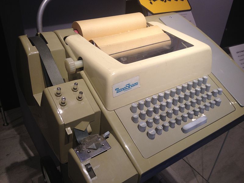 Teletype Model 33 ASR. Image courtesy of Arnold Reinhold via Wikimedia
The teleype was connected to the computer via the KL-11 Teletype Control. This module was controlled via four locations in the PDP-11 memory map:
177560 Teletype Keyboard Status (TKS)
177562 Teletype Keyboard Buffer (TKB)
177564 Teletype Printer Status  (TPS)
177566 Teletype Printer Buffer  (TPB)
The Teletype Keyboard Status register controlls the keyboard via the following bits:
- Bit 0: Reader Enable. Requests that a byte be read from the keyboard or low speed reader.
- Bit 6: Interrupt Enable. A program can set this bit to 1 if an interrupt should be generated when a byte is ready.
- Bit 7: Done. The controller sets this bit to 1 if there is a byte ready to be read from the keyboard buffer.
- Bit 11: Busy. The controller sets this bit to 1 while it is reading the byte from the keyboard / reader.
The Teletype Keyboard Buffer holds the byte read from the keyboard in bits 7 through 0.
The Teletype Printer Status register controls the teletype printer via the following bits:
- Bit 2: Maintenance. When set to 1, causes bytes written to also appear in the keyboard buffer.
- Bit 6: Interrupt Enable. A program can set this to 1 if an interrupt should be generated when the output buffer is ready for another byte.
- Bit 7: Ready. The controller sets this bit to 1 when it can recieve a new byte to send to the printer.
The Teletype Printer Buffer holds the next byte to send to the printer.
Here is an example of how to use these registers to write a program that reads a byte from the keyboard, and writes it to the printer, and repeats this process until halted. This program is written in PAL-11A Assembly Language.
TKS     =       177560          ; TELETYPE KEYBOARD STATUS
TKB     =       177562          ; TELETYPE KEYBOARD BUFFER
TPS     =       177564          ; TELETYPE PRINTER STATUS
TPB     =       177566          ; TELETYPE PRINTER BUFFER
ECHO:   INC     TKS             ; SET READER ENABLE BIT OF TKS
CHKTKS: TSTB    TKS             ; SET PROCESSOR FLAGS BASED ON BITS 7-0
                                ;   OF TKS. NOTE, N IS SET TO THE VALUE
                                ;   OF BIT 7 (DONE)
        BPL     CHKTKS          ; IF N=0 (NOT DONE), TRY AGAIN
CHKTPS: TSTB    TPS             ; SET PROCESSOR FLAGS BASED ON BITS 7-0
                                ;   OF TPS. NOTE, N IS SET TO THE VALUE
                                ;   OF BIT 7 (READY)
        BPL     CHKTPS          ; IF N=0 (NOT READY), TRY AGAIN
        MOV     TKB,TPB         ; COPY VALUE IN KEYBOARD BUFFER TO
                                ;   PRINTER BUFFER
        BR      ECHO            ; START FROM THE TOP
This program tells the teletype controller that it's ready to read the next byte from the keyboard. It then repeatedly asks the controller if it's done reading a byte. When it is done, the program then repeatedly asks the controller if the printer is ready. When it is ready, the program reads the byte from the keyboard, and writes it to the printer. It then starts this whole process over again to read the next byte.
It is no coincidence that the "reader enable" bit is at bit 0, and the "done" and "ready" bits are at bit 7. Instead of setting bit 0 directly using the BIS instruction, it can instead simply increment the value of the register, which sets bit 0 (which starts out with a zero value) to 1. Likewise, using bit 7 allows a program to check the value of the bit by using the TSTB instruction, which sets N to the value of bit 7. This means the programmer doesn't need to use the more cumbersome
CHKTKS:  BIT     #000200,TKS    ; SET Z=0 IF BIT 7 IS SET
         BNE     CHKTKS         ; IF Z=1 (NOT DONE), TRY AGAIN
This technique of repeatedly checking the READY or DONE bits in short, tight loops is called "polling". While the concept is simple, it also means the program is effectively frozen while waiting for a byte from the keyboard device, and frozen again while waitng for the printer to be ready for a byte to print. This isn't a problem in a trivial program like this, but it would be good if the machine could perform other tasks without spending all of its time checking if a device is ready. Most devices are much slower than the processor; the teletype can transfer at most 10 bytes per second- which is 100ms per byte. Even the slowest PDP-11 can execute most instructions in microseconds. Interrupts allow a program to run instructions as normal until a device needs the processors' attention, for example, to read a new byte from the keyboard buffer, or when a byte has been printed and the printer is ready for the next byte. See the interrupts article for more information.