This series of articles will focus on early implementations of the PDP-11 architecture, in particular, the first machine in the series, the PDP-11/20. Later implementations add additional features to the architecture.
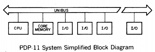
At its most basic, a PDP-11/20 is made up of a "backplane" and a collection of "modules". The backplane is called UNIBUS, which carries a set of 56 signals between each of the modules. The backplane is expandable, since extra backplanes could be wired together. The KA11 processor is a module, and the MM11 memory is another module, as is the KL11 serial console controller and the PC11 high-speed paper tape controller. Eighteen of the signals are used for addressing, sixteen for data, ten for interrupt management, eight for bus arbitration, and the rest for power and ground connections.
The PDP-11 is a "16-bit" architecture: its processor can operate on 16 bits of data at a time. This means a PDP-11 can move a 16-bit value from a register to a memory location with a single machine instruction. Likewise, adding a 16-bit value to another 16-bit value can be done with a single machine instruction. A PDP-11 processor has eight 16-bit registers, known as R0, R1, ..., R7. R7 is also known as the Program Counter, or "PC", which holds the memory location of the next instruction to execute. R6 is also known as the Stack Pointer, or "SP", which is used in very specific ways by certain PDP-11 instructions. The other six registers are available for general use by the programmer.

Each of these registers can hold any 16-bit value. These values can refer to addresses for devices on the UNIBUS1. As a result, the processor can directly reference 2^16, or 65,536 possible addresses. PDP-11 addresses refer to a single byte. Two adjacent bytes are called a "word", and much of the PDP-11 literature will refer to how many kilowords of memory is installed. Most PDP-11 instructions operate on a word at a time, however, there are also instructions that operate on a single byte at a time.
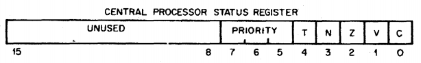
There is also a special register called the "processor status register". This register designates certain bits to indicate the results of previous instructions. These bits have names: C is set to one if the previous instruction caused a Carry, V is set to one if the instruction caused an arithmetic oVerflow, Z is set to one of the instruction result was Zero, N is set to one if the instruction result was Negative, and T is set to one if a "trap" (interrupt) will happen after each instruction (this can be useful while debugging, and is rarely used by most programmers). In addition, the processor status register has a three-bit "processor priority" value that determines if external devices can interrupt the processor. The remaining eight bits of the word are reserved, and are used by later models of PDP-11.
Each module plugged into a UNIBUS backplane is configured to respond to commands when their address appears on the address lines. The memory module is configured to respond to addresses starting at 000000. Other modules, such as the high-speed paper tape controller, are mapped to addresses near the top of the address range. Memory is limited to a maximum of 56 kilobytes (28 kilowords) so there is enough space in the address map for these other devices. A computer with this characteristic is said to have "memory-mapped I/O". This concept was used in later processor architectures like the MOS 6502 and modern ARM processor cores. This is an extremely powerful concept, and greatly simplifies adding new devices and accessing them via user programs.
The listing of devices that shows their addresses is called a "memory map". An example memory map for a basic PDP-11/20 configuration, with 8 kilowords of memory, a teletype console, and a high-speed paper tape reader/punch is:
000000 Core Memory (8 kilowords)
...
037777

177546 Line Frequency Clock

177550 High Speed Paper Tape Reader Status
175552 High Speed Paper Tape Reader Buffer
175554 High Speed Paper Tape Punch Status
175556 High Speed Paper Tape Punch Buffer

177560 Teletype Keyboard Status
177562 Teletype Keyboard Buffer
177564 Teletype Printer Status
177566 Teletype Printer Buffer
Other devices had their own designated addresses, if installed. For example, the LP11 High-Speed Line Printer would listen on the addresses:
177514 Printer Status
177516 Printer Data Buffer
Some devices allowed the operator to use switches on the module to select different addresses- this was usually done if there were multiple controllers on the same type in the same machine. For example, if there were multiple printers attached.
If a device on the UNIBUS needs to get the attention of the processor, for example, if a key is pressed on the Teletype console, the device can assert an "interrupt" signal on the UNIBUS. When this happens, the processor finsihes executing its current instruction, stores the memory location of the next instruction, and sets the program counter to point to a particular location. The location is determined based on which device issued the interrupt. For example, if there's a new character to read from the teletype, the teletype module asserts an interrupt on the bus, and the processor will look up the value at memory address 64. That value should be a memory address loaded with the instructions that can handle reading the contents of the teletype keyboard buffer. Most devices are much slower than the processor, so this "interrupt" feature allows a PDP-11 to continue to run a program while a slow device is waiting for some other external operation to complete, as opposed to forcing the processor to repeatedly ask ("poll") the device if the operation is complete. The PDP-11 reserves low portion of the memory map to be "interrupt vectors" that point to instructions that can handle device interrupts, as well as interrupts generated by the processor itself. For example, if the processor detects a power failure, it will look at the value of address 24, and execute the instructions there. Hopefully before the power goes out.
Notice that the processor can only operate on 16-bit addreses, but the UNIBUS supports 18-bit addresses. This was done to allow for future expansion. Spoiler alert: future PDP-11 models can work with 18- and even 22-bit addresses, using some extra hardware not available for the PDP-11/20. Also, technically, devices were mapped to the top of the UNIBUS address space- devices that asserted the A15 address line, they would also assert A16 and A17. This means the High Speed Paper Tape Reader Status register is really at UNIBUS address 777550. But PDP-11/20 programmers didn't need to know that.